
 We occasionally receive data loggers in for repair that fail their internal self-test. This usually indicates damage to either the internal power supply circuits or to the amplifier/A/D converter. Recently, we received multiple units back from one customer who shared a similar problem with the main power supply. Going back to the customer, we found out that these were all being used to monitor an open pit mine. Since the loggers were in the field, they were powered by solar panels.
The customer said there had been a particularly intense lightning storm at the site which, in addition to the data loggers, had also damaged the solar charge controller. Upon disassembling the loggers we found several of the inductor filters in the power supply were vaporized! This was an obvious indication of a very large and very fast voltage transient on the incoming power. We’ve seen similar damage in the past, sometimes in the power supply and sometimes in the input circuitry including the input relays or multiplexers.
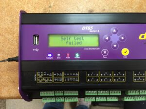
The “self-test failed” message on your device may be caused by indirect lightning damage. A cloud-to-ground lightning bolt involves multiple steps, releasing 30,000 amps and traveling at 1/3 the speed of light. On average, it’s not just one bolt, but 3-4 individual bolts milliseconds apart. Lightning discharges create large voltage variations along the earth’s surface, causing most lightning-related injuries. The high current and fast transient also produce a strong electromagnetic pulse that can damage nearby conductors, such as radios or TVs. This is often the cause of equipment failure, rather than a direct lightning strike.
To prevent or reduce damage, consider using transient voltage suppression (TVS) diodes, like the Littelfuse 1.5KE Series. These devices act as open circuits until voltage reaches a certain level, then they turn on and act as a short circuit. They have a fast response time and can handle up to 200 amps.
To use them on an analog input signal, I usually recommend a “belt and suspenders” approach to provide both protection to ground and protection across the + and – signal lines as shown in Figure 1. Since the signal lines are often floating or isolated from the ground, the 2 unidirectional TVS diodes to the ground prevent either of the signal lines from exceeding the common mode voltage limit of the data logger. The bidirectional TVS between the signal lines prevents the differential voltage between the = and – from getting large enough to cause damage to either the input multiplexers or the signal conditioning and A/D circuits.
For the clamping voltage for the diodes, select a value that is a couple of volts greater than the normal operating voltage of the circuit. For example, if you are using thermocouples where the signal voltage is on the order of millivolts, the lowest value available, 6.8 volts should be OK. If you have a 4-20 mA loop powered by a 24 VDC supply then use a value closer to 30 volts.
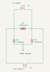
Figure 1 TVS Protection for Analog Inputs
You should also provide protection on the incoming power to the loggers to prevent the sort of damage that was described before. Figure 2 shows one recommended configuration. This will protect both from the excessive voltage across the power lines and from the incoming power to the ground. If the low side of the incoming DC power is already connected to the ground, TVS D2 can be eliminated. Again, the clamping voltage for diode D1 should be a few volts above the nominal power supply voltage and D2 should be as low as possible.
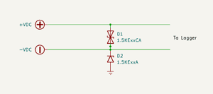
Figure 2 TVS for DC Power Supply
Well, there you have it, my recommendations on what you should do to prevent the next lightning storm from causing the dreaded “Self-Test Failed” error message on your data logger.
Leave a Reply
You must be logged in to post a comment.