dataTaker DT82I

2 Channel Universal Input Industrial Data Logger

  • Up to 6 Analog (±50V) Sensor Inputs
  • 8 Flexible Digital Terminals
  • 2 Serial ‘Smart Sensor’ Ports
  • Programmable Analog Output
  • Modbus for SCADA Connection
  • USB Memory for Easy Data and Program Transfer

$2,275.00

Normal delivery 1-2 weeks

Description

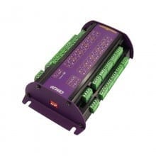
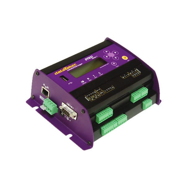
The DT82I Industrial Data Logger

The new DT82I Industrial Data Logger Series 4 version has increased sampling speed, measurement range, and programmable analog output.

The DT82I smart data logger provides an extensive array of features that allow it to be used across various applications. The DT82I is a robust, stand-alone, low-power data logger featuring USB memory stick support, 18-bit resolution, extensive communications capabilities, and a built-in display.

The dataTaker DT82I’s Dual Channel concept allows up to 4 isolated or 6 commonly referenced analog inputs to be used in many combinations. With support for Modbus for SCADA systems, FTP and Web interface, and 12V regulated output to power sensors, the DT82I is a self-contained solution.

Versatile Measurement

Connect an array of sensors through versatile analog and digital channels, high-speed counter inputs, and programmable serial sensor channels.

Temperature, voltage, current, 4-20mA loops, resistance, bridges, strain gauges, frequency, digital, serial, and calculated measurements can all be scaled, logged, and returned in engineering units or within statistical reporting.

Set up sampling, logging, alarm, and control tasks to suit your requirements while interfaces for smart sensors, GPS, and other intelligent devices expand the DT82I flexibility.

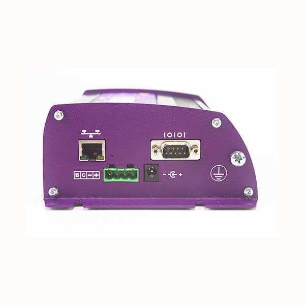
Easy Data Management & Communication

With the standard unit able to store up to 10 million data points (expandable) you can log as much or as little as you need. Overwrite or stop logging once allocated memory is full, archive data on alarm event, copy to USB memory or transfer via FTP/ Email, the choice is yours.

Communications features include RS232 and Ethernet, and connect to the DT82I locally, remotely through a modem, or over the Internet.


Specifications

Analog Channels
Analog Channels 2 Wire w/ Com. Ref. Terminal: 6 Channels
2 Wire Isolated: 4 Channels
3 or 4 Wire Isolated: 2 Channels
Analog Inputs Inter-Channel Isolation: 100 Volts (Relay Switching)
Analog Section Isolation: 100 Volts (Opto-Isolated)
Input Impedance: 160 KΩ, >100MΩ
Common Mode Range: ±3.5V or ±55V
Sampling Integrates over 50/60 Hz Line Period for Accuracy and Noise Rejection
Maximum Sample Speed: 25 Hz
Effective Resolution: 18 Bits
Linearity: 0.01%
Common Mode Rejection: >90dB
Line Series Mode Rejection: > 35dB
Sensor Excitation (Supply) Analog Channels: Selectable 250µA, 213µA or 2.5mA Precision Current Source, 4.5V Voltage Source, or Switched External Supply
General Purpose: Switchable 12V Regulated Supply for Powering Sensors & Accessories (Max. 300mA)
Analog Output Isolated programmable 16-bit DAC: voltage 0-10V or current 0-24mA
Analog Sensors
Thermocouples Type: B, C, D, E, G, J, K, N, R S, T
Calibration Standard: ITS-90
RTDs Materials Supported: Pt, Ni, Cu
Resistance Range: 10Ω to 1MΩ
Thermistors Type: YSI 400xx Series, other Types*
Resistance Range: up to 1MΩOther Thermistor Types are Supported by Thermistor Scaling and Calculated Channels
Monolithic Temperature Sensors Type: LM34 – 60, AD590, AD592, TMPxx, LM135, LM235, LM335
Strain Gauge and Bridge Sensors Configurations: 1/4, 1/2 & Full Bridge
Excitation: Voltage or Current
4-20mA Current Loop Internal 100Ω Shunt or External Shunt Resistor
Digital Channels
Digital Input/Outputs 4 Bi-Directional Channels
Digital Input Type: 4 Logic Level (Max. 20/30 Volts)
Digital Output Type: 3 With Open Drain FET (Max. 30V, 100mA), 1 with Logic Output
Relay Output 1 Latching Relay, contacts (Max: 30Vdc, 1A)
Counter Channels
Low Speed Counters — 4 Counters Shared with Digital Inputs
— 32 Bit Size
— 10 Hz Max Count Rate
— Low Speed Counters do not Function in Sleep Mode
Dedicated Counter Channels — 4 High Speed Inputs
— 32 Bit Size
— 10kHz Max Count Rate
— 2 Logic Level Inputs (Max ±30V)
— 2 Sensitive Inputs (10mV) for Magnetic Pick Ups (Max. ±10V)
Serial Channels
Generic Serial Sensor Available ports: Serial Sensor Port (RS232, RS422, RS485) or Host RS232 Port*
— Flexible Option for Logging From Wide Range of Smart Sensors and Data Streams
— 300 to 115,200 Baud Rate
* If used as a Serial Sensor channel then the Host Port is Not Available for Other Communications
Calculated Channels
General Combine values from analog, digital and serial sensors using expressions involving variables and functions.
Functions Arithmetic, Trigonometric, Relational, Logical and Statistical
Alarms
Condition High, Low or Within Range and Outside Range
Delay Optional Time Period for Alarm Response
Actions Set Digital Outputs, Transmit Message, Execute any DataTaker Command
Scheduling of Data Acquisition
Condition High, Low or Within Range and Outside Range
Number of schedules 11
Schedule rates 10ms to days
Internal Data Storage Capacity: 128mb = approx 10,000,000 data points
Removable USB storage device Type:compatible with USb 1.1 or USB 2.0 drivers, e.g. Flash drive
Capacity: approx 90,000 data points per megabyte
Communication Interfaces
Ethernet Port Interface: 10BasteT (10Mbps)
Protocol: TCP/IP
Host RS232 Port Speed: 300 to 115,200 Baud (57,600 Default)
Flow Control: Hardware (RTS/CTS), Software (XON/XOFF), None
Handshake Lines: DCD, DSR, DTR, RTS, CTS
Modem Support: Auto-Answer and Dial Out
Protocols: ASCII Command, TCP/IP (PPP), Serial Sensor, Modbus (master & slave)
Serial Sensor Port Interface: RS232, RS422m, RS485
Speed: 300 to 57,600 baud
Flow Control: Hardware (RTS/CTS)
Software: (XON/XOFF), None
Protocols: Modbus (master & slave), Serial Sensor
Network TCP/IP Services
Network Ethernet and/or Host RS232 (PPP) Communication Ports
Command Interface Access the ASCII command interface via TCP/IP
Modbus Server(slave) Access current data and status from any Modbus client
Modbus Client(master) Read/Write data from Modbus sensors and devices including PLC’s dataTaker loggers, modbus displays, etc.
FTP Server Access logged data from any FTP client or web browser
FTP Client Automatically upload logged data direct to an FTP server
System
Display and Keypad Type: LCD, 2 Line by 16 Characters, Backlight
Functions: Channel Data, Alarms, System Status
Keypad: 6 Keys for Scrolling and Function Execution
Status LEDs: 4 (Sample, Disk, Attention, Power)
Firmware Upgrade Via: RS232, Ethernet, USB memory
Real Time Clock Normal resolution: 200µs
Accuracy: ±1 min/year (0°C to 40°C), ±4 min/year (-40°C to 70°C)
Power Supply External Voltage Range: 10 to 30 Volts DC
Internal battery: 6Vdc 1.2Ahr lead acid
Peak Power: 12 W (12VDC 1A)
Average power Consumption Using 12Vdc external power source
1 Sec Sampling: 1350 mW
5 Sec Sampling: 500 mW
30 Sec Sampling: 135 mW
5 Min Sampling: 70 mW
1 Hr Sampling: 60 mW
Typical Operating Time from internal 6Vdc, 1.2Ahr battery
1 Sec Sampling: 6.5 hours
5 Sec Sampling: 1 day
1 Min Sampling: 10 days
1 Hr Sampling: 3.5 months
Physical Environment
Construction Powder Coated Zinc & Anodized Aluminum
Dimensions 18.0 cm x 13.7 cm x 6.5 cm (180mm x 137mm x 65mm)
Weight 1.5kg (4kg shipping)
Operating Range Temperature: -45°C to 70°C (Reduced LCD Operation Outside Range: -15°C to 50°C)
Humidity: 85% RH, Non-condensing

Software

dEX 2.0 Logger Software

dEX 2.0 is a software with an intuitive graphical interface for programming dataTaker that allows you to configure, view real-time data in widgets or charts, and retrieve your historical data for analysis.

After installation, you can run dEX 2.0 and establish a connection with your logger through a TCP/IP connection, using Ethernet or USB ports. The cross-platform software will work on major operating systems such as Windows, iOS, and Linux. Utilizing Angular JS which allows one page application for simplicity, this dEX 2.0 draws a new approach to programming and viewing data like never before.

Features:
  • Compatible with previous dEX program
  • Improved UI design with a single centralized page makes it easier to move between functions.
  • Offline configuration (program template creation)
  • Improved programming approach on schedule/channel creation
  • Re-defining alarm declaration
  • Re-defining MODBUS and SDI-12 channel creation
  • Home functions that target multiple loggers

Accessories