
In electrical engineering, Power Factor (PF) is the ratio of real power to the apparent power flowing from the source to the load. For industrial and commercial facilities, a low Power Factor is more than a technical inefficiency—it can impose a significant financial burden. This paper from CAS DataLoggers outlines how to identify PF values, calculate the impact on utility billing, and implement corrective techniques to achieve substantial energy savings and equipment longevity.
How Power Factor Affects Your Utility Bill
Power Factor is measured on a scale of 0 to 1.0 (often expressed as 0% to 100%). It is classified as either leading or lagging, depending on the position of the current waveform relative to the voltage. You can think of it a bit like a kinked garden hose – if the hose is straight, water flows easily through it with minimal pressure drop but if the hose is kinked the pump must work harder to push the same amount of water through. In the case of a low PF, the utility must expend more energy to deliver the same amount of power (current x voltage) to the load.
The Cost of Inefficiency
Most utility providers mandate a PF threshold, typically between 95% and 96%. If a facility falls below this level, the provider imposes a Reactive Power Fee.
- Why the fee exists: A low PF indicates an inefficient load that draws “reactive” (non-working) power. The utility must generate and transmit this extra power, even though it performs no actual work, putting a strain on the grid infrastructure.
- The Alignment Principle: In an ideal AC circuit, voltage and current are perfectly aligned (Unity). However, inductive loads (like motors and transformers) cause the current to lag behind the voltage. This misalignment forces the system to draw more current to perform the same amount of work.
Calculating Power Factor: The Power Triangle
To calculate Power Factor, we must understand the relationship between three types of power:
- Real Power (P): The actual power used to perform work, measured in kilowatts (kW).
- Reactive Power (Q): The “non-working” power required to maintain magnetic fields in inductive equipment, measured in kilovolt-amperes reactive (kVAr). This is because physics says the current passing through an inductive load like a motor cannot change instantly i.e. the inductance “reacts” to changing currents by opposing the change.
- Apparent Power (S): The vector sum of Real and Reactive power, measured in kilovolt-amperes (kVA).
You can use these three aspects to derive the Power Factor. See Figure 1 below.
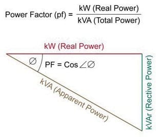
Figure 1 – Calculating Power Factor
In an electric power system, a load with a low power factor draws more current than a load with a high power factor (near 100%) for the same amount of useful power transferred. These higher currents increase the energy lost in the distribution system and also require larger wires and other equipment. In other words, your Power Factor percentage shows you how much of the total current is being used to do real work. For example, a PF of 0.80 means that only 80% of the current supplied to your facility is doing useful work, while 20% is being wasted as non-working reactive power.
The 6 Strategic Benefits of PF Correction
- Direct Utility Savings: Eliminating penalty fees can reduce monthly bills by up to 20%. Many utilities calculate the penalty based on the Peak Demand (kVA) rather than a flat fee, meaning a low PF multiplier can exponentially increase the highest part of your bill.
- Increased System Capacity: Improving PF reduces the current draw, effectively “freeing up” capacity on your existing transformers and switchgear.
- Carbon Footprint Reduction: Higher efficiency leads to lower energy demand, directly reducing $CO2 emissions.
- Reduced I2R Losses: Lowering the current reduces heat losses in cables and distribution equipment.
- Equipment Longevity: Reduced heat in motors and transformers prevents premature insulation breakdown and extends service life.
- Improved Voltage Regulation: PF correction reduces voltage drops in long cable runs, ensuring motors start reliably and operate within their rated specifications.
Diagnostic Phase: Using Power Data Loggers
 Before implementing correction, you must conduct a Power Factor Study. A 3-phase Power Data Logger is used to monitor voltage and current channels simultaneously. These devices capture:
- Min/Max/Average values over time
- Harmonic Distortion profiles
- Load Profiles to identify when the PF is at its lowest
This data is the foundation of a successful energy efficiency analysis and ensures that correction equipment is sized accurately.
Corrective Techniques: Raising Your Power Factor
Correcting PF involves supplying reactive power of the opposite sign to cancel out the effects of the load.
Passive Correction
Linear loads with a low power factor can be corrected using a passive network of capacitors or inductors. In the electricity industry, inductors are said to consume reactive power and capacitors are said to supply it; these devices alter the phase relationship between the voltage and current during AC line cycle to force them back in phase. For example, you can offset the inductive effect of motor loads by using locally-connected capacitors. If a load has a capacitive value, connect inductors (also known as reactors in this context) to correct the power factor.
Capacitors prevent equipment from having to draw reactive power from the grid. Non-linear loads such as rectifiers distort the current drawn from the system. In such cases, you can use active or passive power factor correction to counteract the distortion and raise the power factor. The devices correcting the power factor may be located at a central substation, spread out over a distribution system, or built into power-consuming equipment.
- Capacitor Banks: Most industrial loads are inductive (motors). Adding locally connected capacitors supplies the necessary reactive power, preventing it from being drawn from the utility grid.
- Operational Changes: Before investing in hardware, ensure motors are not oversized for their loads and avoid running idling motors for extended periods.
Active & Advanced Correction
- Automatic PF Correction Units: These units use a controller to switch capacitor blocks in and out of the circuit based on real-time demand.
- Synchronous Condensers: Utilizing an unloaded synchronous motor to provide variable reactive power by adjusting field excitation to create a leading power factor.
- Static VAR Compensators (SVC) & STATCOM: For high-voltage or rapidly fluctuating loads, these solid-state electronic devices provide near-instantaneous compensation with lower maintenance than mechanical systems.
Engineering Note: Correction elements must be applied following a detailed engineering analysis. Improperly placed capacitors can cause harmonic resonance, voltage fluctuations, and system instability. In the US, IEEE 519 (the standard for harmonic control in electric power systems) provides the guidelines for design of PF control systems.
Summary:
Measuring and correcting Power Factor is one of the most effective ways to realize immediate energy savings and protect your electrical infrastructure. Through data-driven analysis with professional logging equipment, facilities can move toward “Unity,” ensuring every dollar spent on electricity is going toward productive work.
For more information on Current, Voltage and Power dataloggers, or to find the ideal solution for your application-specific needs, contact a CAS Data Logger Applications Specialist at (800) 956-4437 or request more information.