
 Data logging from sensors that provide a pulse output such as flow meters, speed sensors, electrical power meters, and switches is a common requirement. These applications may require the measurement of a rate, for example, gallons/minute or RPM or they may require totalizing the pulse count to determine flow volume, distance traveled, kWh used, or machine cycles. This application note guides the selection of the appropriate measurement method for capturing data from these sensors using a data Taker DT8x data logger.
The dataTaker DT8x family of data loggers is extremely flexible, and they allow the measurement of pulse output sensors using several different methods. However, it is not always obvious which method should be used or which might provide the best results. This tech note is intended to provide some background on the techniques we have used to capture data from these sensors.
Sensor Signal Output Types
When choosing which to use, it is essential to know the electrical characteristics of the output pulses that are coming from the sensor. There are 4 common output types:
1. AC voltage output devices: These are not true pulse output sensors but are commonly found in anemometers and gear tooth magnetic pickup sensors. The signal output is an AC sine wave that varies in frequency and amplitude based on speed. In some cases, the voltage output can exceed 90 VAC peak-to-peak.
2. Dry contact devices: These are simple switches. This could be a mechanical switch (e.g., a micro switch or a reed switch) that is periodically closed, for example, by a magnet passing by (like on a door opening switch). In this case, the switch needs some sort of external excitation to generate a signal that can be measured by the data logger. A standard technique is to use a resistor (called a pull-up resistor) with one end connected to a voltage source and the other end connected to one side of the switch; the other side of the switch is connected to the ground of the voltage source.
3. Open collector output devices: These are very common in industrial automation systems and come in two flavors: NPN and PNP. In an NPN output, the emitter of a transistor is connected to the ground, so the output (collector) switches from on to off, effectively creating a series of open and closed connections to the ground as the sensor switches state. A PNP output is the opposite; the emitter is connected to the supply voltage, so the output switches between the open and the power supply voltage as the state changes. Like the dry contact switch, these sensors require an external source to create the pulse waveform. Proximity sensors are one of the most common types of sensors that use open collector outputs.
4. Voltage Output Sensors: These sensors provide a true voltage pulse output. A common type uses TTL standard logic voltage levels; a low (off) is defined as a voltage below 0.8V, and a high (on) is a voltage above 2.0V. The output of these sensors can be fed directly into a digital input or counter circuit of the appropriate type. In industrial systems, you may find voltage outputs that switch between 0 and 24 VDC.
Data Logger Pulse Measurement Methods
The DT8x family of loggers offers 3 ways to measure a pulse output sensor s:
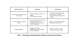
• Frequency measurement using an analog channel
• Low-speed counter using a digital channel
• High-speed counter channels
Each of these has certain advantages and disadvantages that make it more or less suitable for a particular sensor type.
1. Frequency Measurement
Any of the analog input channels of the data logger can be used to measure the frequency of a repetitive pulse train using the “F” channel type. Internally, the logger has a very accurate time base reference that is used to measure the time between 2 zero crossings of the input waveform.
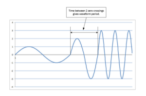
Figure 1 – Zero Crossing Measurement
By taking the inverse of this time the logger can calculate the frequency of the signal: f=1/(time between zero crossings)
An advantage of using the frequency measurement is that it can accommodate signals up to 50V p-p in series 4 loggers. To improve the reliability of the measurements, it’s best to set the logger to a fixed measurement range using the gain lock command, GLnnn. Also, the default settings allow measurement of a range of frequencies between 33 Hz and 20 kHz making this method suitable for fast pulses.
The main disadvantage of the frequency measurement method is that it relies on the voltage passing through 0.0V which has 2 implications:
a. In the case of a dry contact, open collector, or voltage output sensor, if the voltage does not pass through zero volts, i.e. the sensor switches from 0.5 to +5.0 volts, the frequency measurement will not be reliable. It is possible to work around this by using the reference offset option, 2V, with the F channel type which will apply an offset voltage to the measurement circuit to offset the crossing point to +2.5V.
b. The data logger may time out if the pulse frequency is too low, resulting in an “Under range” reading. The maximum time between zero crossings is 30 milliseconds but can be increased with a sample period as a channel factor option. However, this may affect the data logger’s ability to process other commands.
2. Digital Input Used as Counters
Any of the digital inputs 1D-8D (4D in the case of the DT82) can be used as a low-speed counter. Be aware that the first 4 digital inputs 1D-4D (or 3 inputs 1D-3D in the case of the DT82x) are electrically different from the remaining digital inputs, 5D-8D. The first 4 (3) inputs have a 47k ohm pull-up resistor to the internal 3.3V digital power supply. This makes them especially suitable for use with dry contact switches or NPN open collector sensors. The pull-up resistor will cause the digital input to go to a high voltage when the switch is open or the output transistor is off and will allow the input to go to 0.0V when the switch is closed or the output transistor is turned on. These channels are also compatible with sensors with a TTL output.
The other digital inputs have a 200k ohm pull-down resistor to ground. These inputs are well suited to PNP output sensors or the measurement of sensors that have a voltage output in the on state but are open in the off state. In the absence of an input voltage, the digital input will be 0.0 V or low, and when the sensor switches state, the external voltage from the sensor will cause the input to go high and increment the count. If it’s necessary to use these inputs with a dry contact or NPN output sensor, an external voltage source will be required to pull the input high to allow the data logger to count correctly.
As with the frequency measurement, there are several considerations when using digital inputs as counters.
a. The counters are implemented in software by scanning the digital inputs every 20 milliseconds to see if the state has changed. This means that the width of the pulse must be greater than 20 milliseconds or the logger may not detect the transition between scan times.
b. Based on the scan rate, a maximum measurable pulse frequency, assuming a 50% duty cycle, is about 25 Hz. Pulses of a higher frequency will not be properly counted.
c. When the data logger is asleep, the processor is in a low power state and the channels are not scanned so this method cannot be used to measure pulse counts over longer periods (the default is 30 seconds) when the logger is operating off battery or in a forced sleep mode which causes the logger to go into sleep mode between samples. If the low-speed counters need to be used continuously, the logger should be externally powered and the sleep mode should be disabled by setting parameter P15=2.
3. High-Speed Counter Controls
All of the loggers have 4 dedicated high-speed hardware counter channels (8 in the case of the DT85 S3/S4 models). These channels are capable of counting pulses as fast as 10 kHz. These channels are similar to digital channels 1-4 in that they incorporate a weak pull-up resistor that allows them to be used with dry contact or open collector output sensors as well as TTL output sensors. In addition, channels 1 and 2 can measure low-level signals from millivolt output sensors, such as those with an inductive pickup, using the low threshold (LT) option. This sets the off/on the threshold at <2 mV and >7 mV respectively.
The hardware counters will function if the logger is asleep allowing them to be used over longer sampling intervals however, the maximum count is limited by the width of the counter registers which is 16 bits equivalent to 65536 counts. If more pulses than this occur within the sample interval or if the count is allowed to accumulate over a long period it will overflow and restart back at 0. To prevent a loss of counts, configure the logger to read the high-speed counters frequently enough so that there will never be more than 65536 pulses within any sampling interval. For example, if the average counter input frequency is 100Hz then the DT80 must be programmed to wake at least every 65536/100 seconds (about every 10 minutes).
Also, when used with a dry contact (voltage-free) input where the input is not actively driven to a high state but rather is forced to a high by the internal pull-up resistor, the inputs are effectively filtered to “debounce” the input from contacts in mechanical switches or relays. This limits the maximum count rate to about 500 Hz when used with a voltage-free input.
Flow Meter Example
With all of this in mind let’s consider a common application of a water flow meter. A common turbine flow meter has a simple dry contact output that is triggered when a magnet embedded in one of the turbine blades passes by a reed switch. For this meter, a flow each gallon of flow produces 50 pulses. Therefore, a flow of 200 gallons per minute (GPM) produces 200 * 50 = 10,000 pulses in a one-minute interval or a frequency of 10,000 pulses/60 seconds = 167 pulses/second. For this application, it is necessary to record the flow every 10 seconds so our count for a 10-second interval would be 10 * 167 = 1670 pulse at a 200 GPM flow rate.
Since this sensor has a simple switch output and the pulse frequency is in the range of 100-200Hz, it is easiest to wire it to one of the high-speed counter inputs so let’s use counter 1.
In deTransfer the program would be:
BEGIN”JOB1”
CATTN
‘Spans and polynomial declarations
S1=0,200,0,1670”GPM”
‘Global declarations
RS1S
‘schedule definition
RA(“B:”,ALARMS:OV:100KB,DATA:OV:1MB)10S LOGONA GA
1HSC(R,S1,”Flow”)
END
Here, we have configured the scaling to take into account the 10-second sample interval by multiplying the sensor output by the interval, i.e. a flow rate of 200 GPM will produce 167 pulses/gallon x 10 seconds sample interval = 1670 pulses in the sample interval. Also, we have used the R option in the counter command to reset the count back to 0 after reading the count.
The setup in Delogger would be:
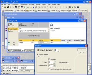
Note the resetting option has been enabled to reset the counter to 0 after each reading. It is not apparent, but the scaling has been adjusted per the previous example.
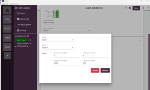
The setup in dEX would look like this:
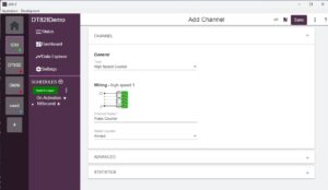
The reset counter option has been enabled for this counter to reset the count to 0 after the measurement is made.
The scaling looks like this:
Conclusion
This article has provided an overview of measuring pulse outputs from various sensors using dataTaker DT8x data loggers. By understanding the four common pulse output types—AC voltage, dry contact, open collector (NPN and PNP), and voltage output—users can effectively match their sensors with the appropriate measurement technique. The article detailed three such techniques: frequency measurement, low-speed counting, and high-speed counting, highlighting the advantages and limitations of each. Careful consideration of sensor characteristics, signal frequency, and data logger capabilities is crucial for accurate and reliable data acquisition. We hope this guide helps you select and implement the optimal measure approach for their specific pulse output sensor application.