
 Measuring Material Deformation with Electrical Signals
- Strain Gauge Measurement
- What is Strain? Strain is a dimensionless quantity that describes the deformation of a material. It represents the relative change in length (or dimension) due to an applied force and is typically expressed in microstrain (μεm/m).
- How Does a Strain Gauge Work? A strain gauge is a sensor that converts mechanical strain into an electrical signal. It’s typically a thin wire or foil arranged in a grid pattern, bonded to the surface of the object being measured. When the object experiences strain, the length of the wire or foil changes slightly, altering the electrical resistance of the gauge. Strain gauges are available in a variety of configurations to measure the strain along a single axis, or multiple axes or to measure torque/shear.
- Gauge Factor (GF): This is a measure of the gauge’s sensitivity to strain. It’s the ratio of the fractional change in resistance to the fractional change in length (strain). The gauge factor is defined as:
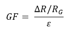
Where RG is the unloaded resistance of the gauge, ΔR is the change in resistance and ε is the strain. Typically, the gauge factor is approximately 2, and a full-scale value for ε is .001 so the value of ΔR/R will be .002, or for a common 350-ohm strain gauge a change of .7 ohms. To measure a change of 1% you would need to measure a resistance change of .007 ohms in base resistance of 350 ohms or about 20 parts per million.
- Wheatstone Bridge: Because it is not practical to measure such small changes in resistance directly, strain gauges are often used in a Wheatstone bridge circuit.
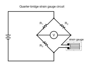
In this circuit, the 3 bridge completion resistors R1, R2 and R3 balance the circuit so that the output voltage is zero with no load applied. Then the output signal can be amplified by the measuring device and very small changes in strain gauge resistance caused by the applied force and measured more easily.
2. Temperature Effects
Strain gauges can be sensitive to temperature changes, which can affect the apparent measured strain. This is because both strain and temperature cause changes in the electrical resistance of the gauge material. Unfortunately, the change in resistance of the gauge material is often nearly the same order of magnitude as the change in resistance due to the applied strain which can make getting accurate strain gauge measurement very difficult in cases where the temperature changes by even a few degrees during the test. There are several ways to address this problem:
a. Using the Wheatstone bridge measurement with bridge completion resistors that match the temperature coefficient of resistivity (TCR) of the strain gauge or using dummy gauges with no applied load as the completion resistors. Since all of the resistors change at the same rate, the bridge will remain balanced (zero output) as the temperature changes.
b. Using temperature-compensated strain gauges. These gauges are designed such that the thermal expansion coefficient of the material/sample is designed to cancel the TCR of the gauge itself. This will minimize any apparent resistance change due solely to temperature.
3. Excitation
The strain gauge bridge circuit requires an electrical current or voltage source for excitation. Also is a ratio-metric device which means that the output voltage changes as the excitation changes. The selection of type of excitation (voltage or current) depends on the specific bridge configuration, the distance between the measurement device and the strain gauge along with the type of wire and the desired measurement characteristics. Factors to consider include:
- Voltage excitation is the easiest to implement and interpret the results. However, because the output voltage is a function of the excitation voltage, it requires a very stable, low-noise voltage source. With long cable runs, the voltage drop in wires can cause measurement errors that must be compensated for. Typical excitation voltages are 5 or 10 VDC but it is important to make sure that the resulting current does not cause self-heating in the strain gauge.
- Current excitation is better when there are long cable runs and it can offer better noise immunity. However, a constant current source can be more complex, and interpreting the results may be more complex.
4. Measurement System
The Wheatstone bridge output voltage is a function of the change in resistance of the strain gauge measurement due to strain. Since the full-scale output of a typical strain gauge is on the order of 3 to 5 mV/V of excitation, with a 10 VDC power supply this would represent 30-50 mV at the maximum recommended strain. The data logger or data acquisition system then amplifies this signal and converts the voltage into a digital value. Depending on the system, it may do additional processing to provide a representation of strain based on the calibration factor (gauge factor and bridge configuration). To improve accuracy, many systems will also sample the excitation voltage since any variation in this value will directly affect the output owing to the ratio-metric nature of the strain gauge discussed in the previous section. Due to the low voltage level of the output signal, averaging or filtering can be used to reduce the noise in the measured value. For example, 60/50 Hz line cycle filtering can be used to remove the effects of EMI from nearby AC power sources.
Conclusion
Strain gauges offer a versatile and sensitive method for measuring mechanical strain. By understanding the principles of gauge operation, the effects of temperature on the measurement, methods of excitation, and the requirements of measurement systems, users can make accurate strain measurements. Careful selection of gauge type, bridge configuration, and data acquisition system is crucial for optimal performance.